|
Please look at https://gitlab.inria.fr/glose/flight-controller-language-demonstrator for all the sources (including both the FCL language and this document). |
The goals of this demonstrator is to provide general guidelines about how to use GEMOC technologies in order to build the tooling for a language.
The provided tooling covers several concerns such as:
-
Model edition (including textual and graphical edition)
-
Model execution (including model debugging).
It is illustrated on a realistic language: a language for designing drone flight controllers.
As explained in https://download.eclipse.org/gemoc/docs/nightly/index.html , building the tooling for a language highlights 2 mains roles: language engineers and modellers.
-
Language engineers are the users that design executable DSLs using a metalanguage to define their execution semantics. These users also develop domain- specific tools for their languages, such as editors, validators, compilers… When possible they reuse and/or extend generic tools provided by metalanguage engineers.
-
Modelers are the users that design models conforming to executable DSLs. Depending on how supported a given executable DSL and the metalanguage used to define its execution semantics are, modelers will have access to a number of tools to aid them in their endeavor.
The GEMOC Studio used in this demonstrator offers dedicated workspaces and tooling for each of these roles that are referenced as GEMOC Language workbench for the tools for language engineers and GEMOC Modeling Workbench for the tools for _Modelers.
In this document, we may have to switch between these workbench in order to show the result of the language workbench in the final modeling workbench:
-
items or roles relative to the Language Workbench or involving the Language Engineer are identified with the following icon :

-
items or roles relative to the Modeling Workbench or involving the Modeler are identified with the following icon :

|
This switch is required only during the development, once finished, one can build a standalone eclipse product dedicated to the Modelers that contains only the final dsl tooling. For FCL, one can use the following update site to add FCL tooling to an existing Eclipse and get a Modeling workbench. |
|
This document presents the actions in a sequential order corresponding roughly to the first time each of these actions was started. However, the development is actually iterative. Actions of the last steps may require changing or improving element done in previous steps. |
1. Flight Controller Language - FCL
1.1. Language Overview
When building a flight controller, most people directly write the controller logic in the target platform language. For example, they write in c when targeting ardiuno hardware.
Thanks to GEMOC we build a language dedicated to specify the logic for such code.
A end user of such language would then have a higher level of abstraction and better editing support allowing her to be more efficient when writing complex logic.
The FCL is intended to specify relatively small actions (which might be complex in terms of control command laws on the rotors and sensors) and basic plans. These actions will be organized in modes., and how to switch from one mode to another, and which concrete actions are run. For instance, typical basic modes that would be defined for a copter would be inspired by the ones defined in ardupilot flight controller http://ardupilot.org/copter/docs/flight-modes.html.
1.2. Repository Content Summary
The sources in git contains the following content:
1.2.1. FCL Specifications
The specifications of FCL are in fcl-implementations.
The folder fcl contains the projects building a language that is not executable yet, (ie. the common part of various behavior implementation)
-
fcl/fr.inria.glose.fcl.dsml project contains the GEMOC declaration of the fcl common part. It is mainly used to drive the helper wizards;
-
fcl/fr.inria.glose.fcl.model project contains the structural definition of the language (see Section 2.1);
-
fcl/fr.inria.glose.fcl.design contains the graphical editor specification of the language (see Section 2.2.2);
-
fcl/fr.inria.glose.fcl.xtext contains textual editor specification of the language (see Section 2.2.1);
-
fcl/fr.inria.glose.fcl.xtext.ide and fcl/fr.inria.glose.fcl.xtext.ui contain the code for integrating the textual editor in Eclipse;
-
fcl/fr.inria.glose.fcl.xtext.tests and fcl/fr.inria.glose.fcl.xtext.ui.tests projects contains a base for unit tests.
The folder commons contains the projects that are not specific to FCL
-
commons/org.javafmi project contains the java driver allowing to load FMI/FMU;
The folder alefcl contains the projects defining an executable language for FCL writing using ALE.
-
alefcl/fr.inria.glose.fcl.alefcl.xdmsl project contains: the GEMOC declaration of the executable FCL: ALEFCL; the ALE extension that adds the behavioral semantics on top of the FCL base ().
-
alefcl/fr.inria.glose.fcl.alefcl.xdmsl.design project contains the debug and animation extension to fr.inria.glose.fcl.design dedicated to the ALEFCL language.
-
alefcl/fr.inria.glose.fcl.alefcl.vm.mdodel project contains some additional extension written in ecore defining some VirtualMachine concepts used by ALEFCL.
1.2.2. Demonstration Controllers
Some FCL model examples are located in: model_examples.
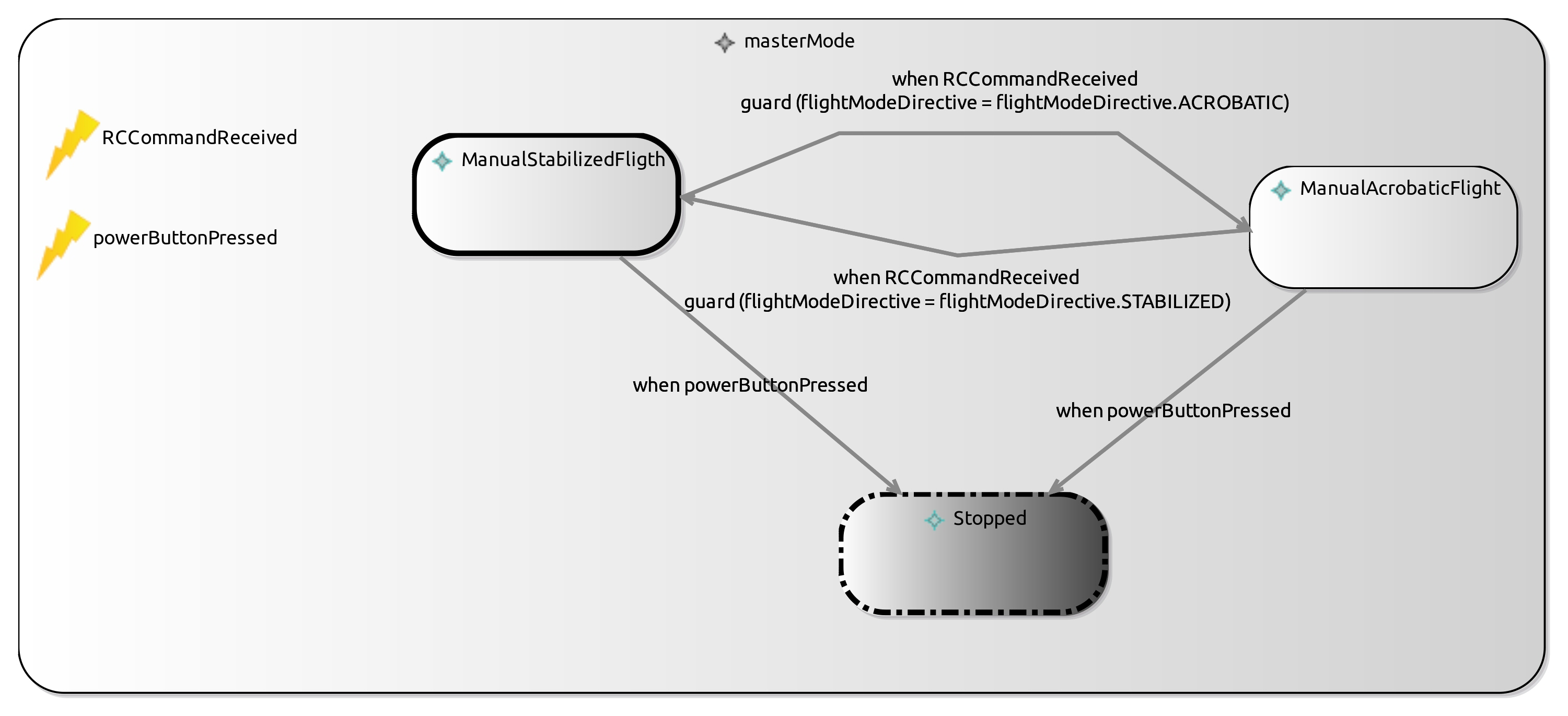
The demonstrator main example is located in fr.inria.glose.miniquadcoptercontroller.demo_v0. It models a Quadcopter flight controller with two modes: a manual acrobatic mode and a manual stabilized mode.
2. Scenario #1: Building an Executable Modeling Language
This scenario demonstrates the ability of the GEMOC Studio to help a language designer to build her own modeling language, including the concepts (aka. abstract syntax), the textual and/or graphical representation (aka. concrete syntax), and the meaning of those concepts over the time (aka. behavioral semantics). The behavioral semantics is specified in the form of a virtual machine allowing the execution of a conforming model.
As an outcome of such a scenario, the demonstrator shows how to automatically get a domain-specific modeling and execution environment from the specification of the modeling language. The use of resulting environment is demonstrated in Chapter 3
2.1. FCL Metamodel Design
During this phase the ![]() Language engineer captures the concepts the
Language engineer captures the concepts the ![]() Modeler will
be able use.
Modeler will
be able use.
The main concerns of the ![]() Language engineer during this step will be to specify a
class diagram with a special focus on:
Language engineer during this step will be to specify a
class diagram with a special focus on:
-
the list of concepts
-
their relationship. This includes the containment relationship which is used by many of the generic tools in order to provide efficient default implementations.
2.1.1. FCL Ecore
⇒ ![]()
Basically, FCL allows to model a DataFlow where the enabled Functions are filtered by a StateMachine defining "Modes".
Figure 3 shows the relations between the major concepts:
-
FCMModel, the root of the model; -
ModeStateMachine, the state machine controlling modes; -
Function, the functions of the dataflow; -
FunctionPort, the input and ouput port of functions; -
FunctionConnector, the connections between ports; -
Event, the event that can be used to trigger mode change; -
DataType, the primitive type of the data used in the model; -
Action, the action done when processing functions or when triggering mode changes; -
Expression, the expression used in actions and in the statemachine guards.
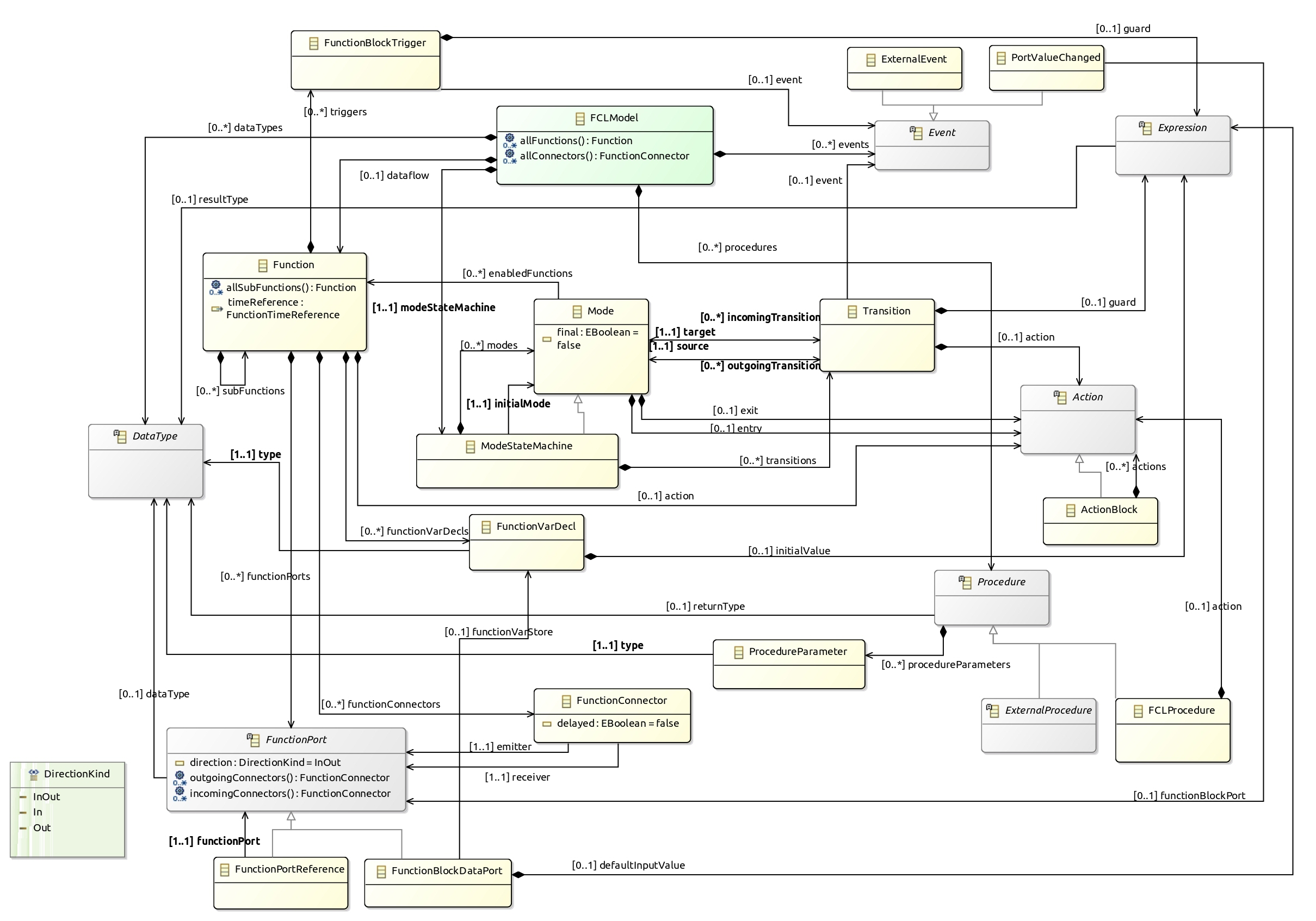
Figure 4 shows the ModeStateMachine concepts. Basically, it models a statemachine controlling enabled Functions. The ModeStateMachine is composed of Modes that enable a set of Function. Changing mode is done by going through Transition where these Transition are guarded by an Event and/or an Expression. Some Action can be defined when a Transition is fired or when entering or leaving a Mode.
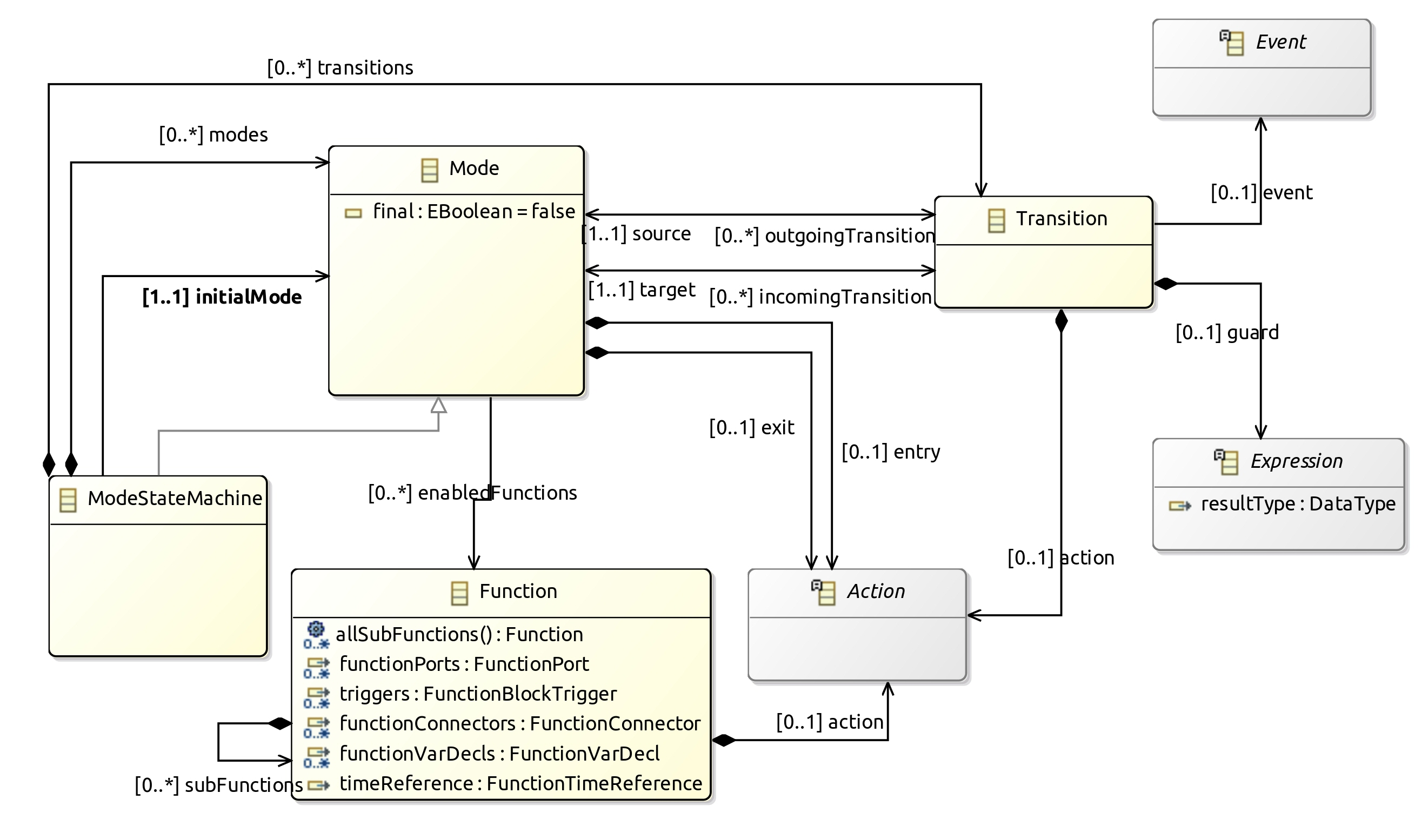
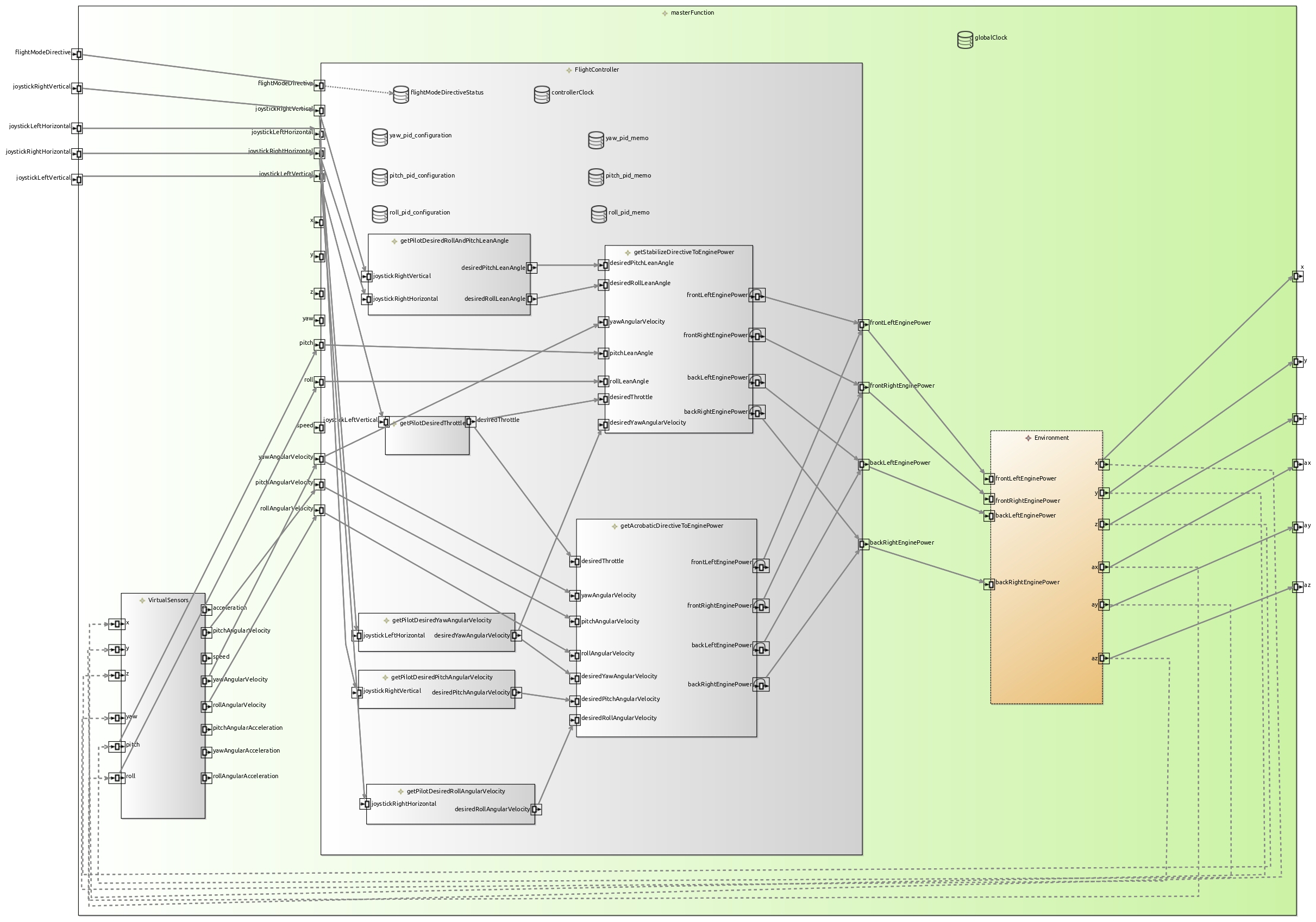
Figure 5 shows the Function concepts. Basically, it models a data flow between Functions. These Functions declare DataPorts that can be connected through FunctionConnectors. Each Port may be In, Out or InOut. A Function can declare sub functions.
FMUFunction and FMUFunctionBlockDataPort are specializations dedicated to handle the connect a blackbox Function that can communicate using FMI/FMU protocol.
Basic Function declare an Action whose role is to specify the value to set on Out ports from In ports.
Functions can declare variables that are local to the function. It allows to use them (read/write) from Expressions and Action (ie. Event, procedure body, …). They can be associated to a port but can also have their own modification lifecycle (for example, a nested function modifying a value in its parent function…).
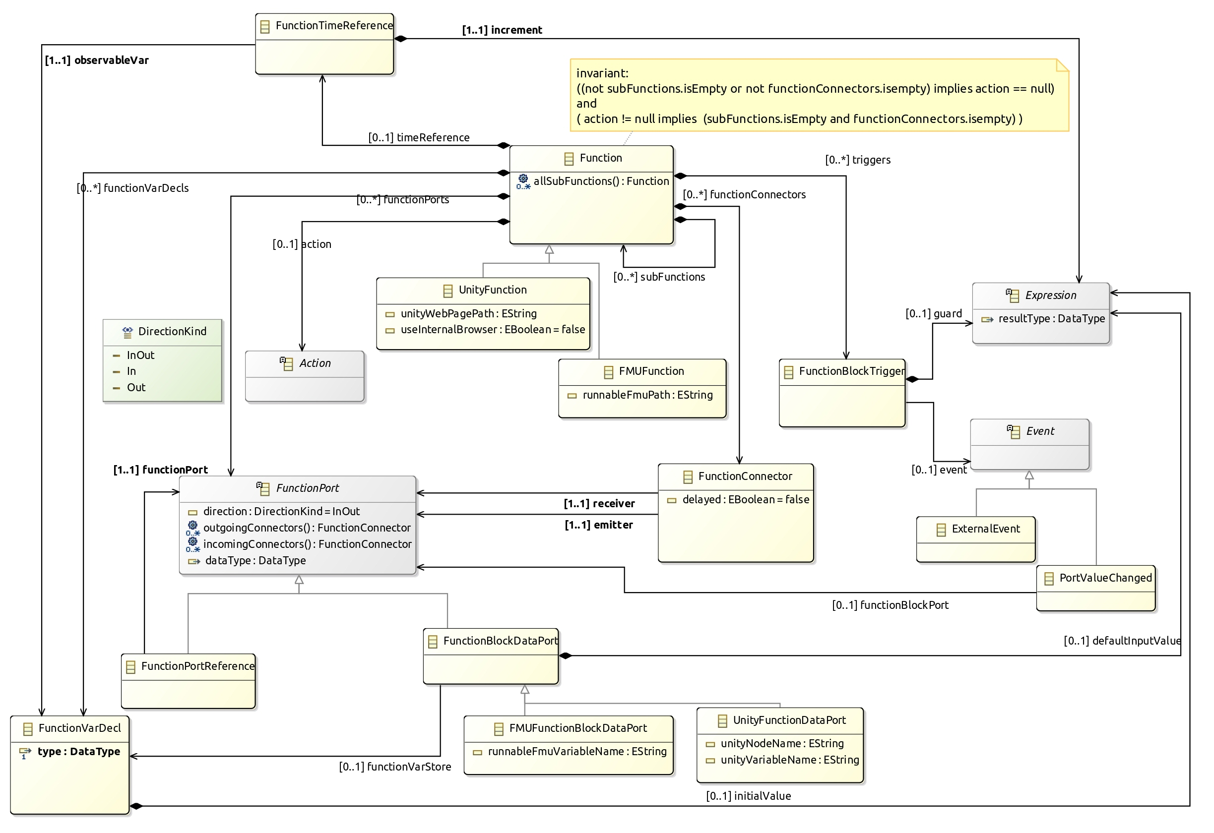
Figure 6 shows the concepts supported to define the Expression in various places in the DSL. Expression are typed, this allows several type verification either statically and at runtime (see also Figure 8).
BinaryExpression defines a set of operators allowing to combine 2 expressions.
UnaryExpression defines some simple operation on a given expression.
CallConstant allows to define constant in the model (for each of the supported data type).
CallDeclarationReference allows to get the current value associated to one of the CallableDeclaration elements of the language: a port of a Function (FunctionPort), a local variable declaration (VarDecl), a variable in a function (FunctionVarDecl) or an enumration literal.
Similarly to CallDeclarationReference, CallPrevious allows to get the previous value associated to one of the CallableDeclaration elements of the language.
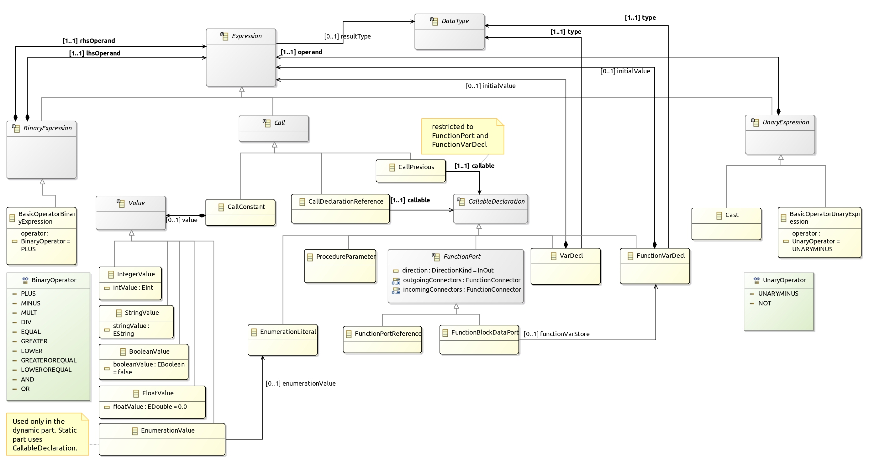
Figure 7 shows the concepts supported to define the Action in various places in the DSL. It basically uses Expression in order to provide the value to set in function ports and function variables.
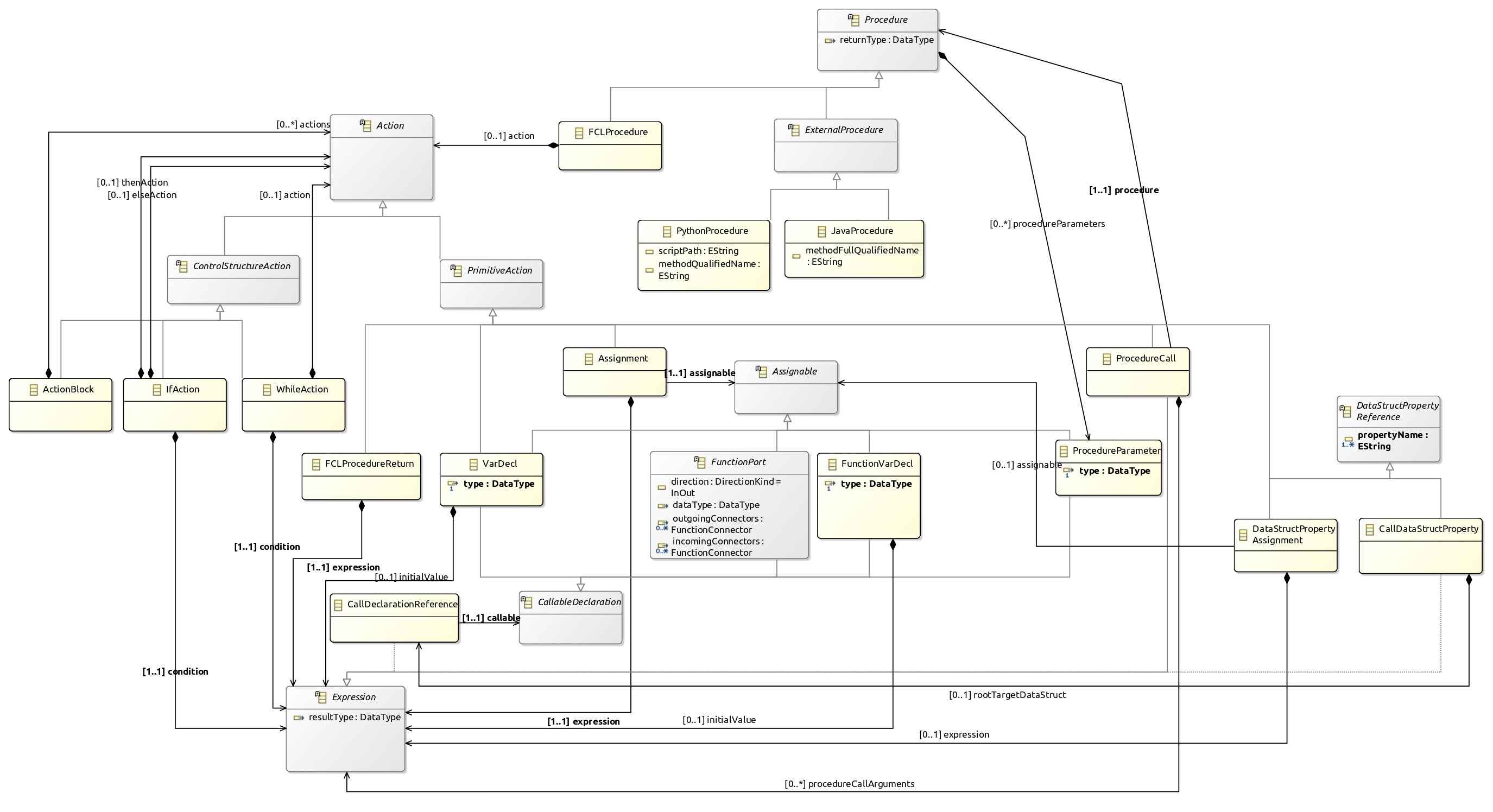
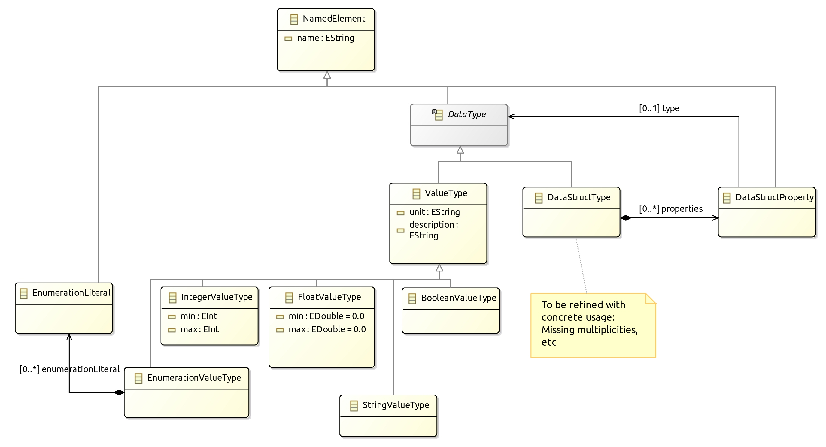
Figure 8 shows the primitive types that the
![]() Modeler can use when she define types in the model.
These types allow validation and early error reporting when associated with
validation rules (see Section 2.2.4).
Modeler can use when she define types in the model.
These types allow validation and early error reporting when associated with
validation rules (see Section 2.2.4).
2.1.2. Basic Tree Editor
⇒ ![]()
Up to this point, the ecore provide a minimalistic model edition support using a tree representation. Figure 9 shows this tree editor on the basic quadcopter controller.
This tree editor is convenient during the early steps of the ecore definition as is allows to create sample models and manually check the expressivity of the language.
2.2. Editors Design
The demonstrator illutrates the developement of two editors that collaborates:
-
a textual editor allowing to fully write the model in a modern text editor with completion, syntax highlighting, error/warning reporting.
-
a graphical editor allowing to display and edit some part of the model. This editor doesn’t intend to provide a graphical representation for all concepts but will open the textual editor when required. (for example, the
ExpressionorActionpart of the model are displayed/edited using a textual syntax only)
|
Even if this demonstrator focuses on more sophisticated editors (Textual and graphical), it is easy to customize the basic tree editor (see Section 2.1.2) to provide nicer labels and icons. Simply do a generate Model edit and
generate Model editor on the genmodel file. Then change the gif images and edit
the Do not forget to add a |
2.2.1. XText Editor
Starting an XText editor for FCL is done by doing:
-
Right Click on the dsl project
-
GEMOC Language → Create Xtext editor project for Language
-
project name: fr.inria.glose.fcl.xtext
-
Name: fr.inria.glose.fcl.xtext.FCL
-
| You can also do a File → new → project → xtext project from existing ecore models |
This creates the project: fr.inria.glose.fcl.xtext
The file fr.inria.glose.fcl.xtext/src/fr/inria/glose/fcl/FCL.xtext contains the
grammar allowing to parse *.fcl files.
The default grammar rules generated by the project creation wizard are functional but doesn’t suit our needs. So they are customized to provide a friendlier textual syntax.
A Right click on the xtext file → Run As → Generate Xtext artifacts will update the java code for the parser.
| reference documentation https://www.eclipse.org/Xtext/documentation/301_grammarlanguage.html |
After modification (see fr.inria.glose.fcl.xtext/src/fr/inria/glose/fcl/FCL.xtext),
it now supports operator precedence, and a syntax less verbose than the default one.
Xtext allows to define formatting rules. These rules readjusts the spaces, indentation and line breaks when using Ctrl+Shift+F in the editor. The formatter code in conveniently written in the form of rules in FCLFormatter.xtend
|
While providing formatting rules is only a minor addition when using only xtext editor, this becomes important to have it if the graphical views also allow to edit the model. This ensures that the newly created elements will be properly displayed in the textual editor. |
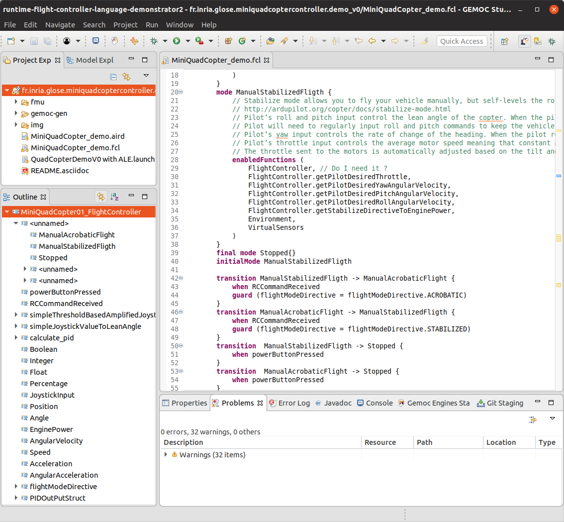
⇒ ![]() Section 3.1.1 shows the resulting XText editor in action.
Section 3.1.1 shows the resulting XText editor in action.
2.2.2. Sirius Editor
To initiate a first diagram for FCL:
-
Right Click on the dsl project
-
GEMOC Language → Create Sirius editor project for Language
-
project name: fr.inria.glose.fcl.design
-
-
Next → Next → check the box create a plugin using one of the following template → Select FCLModel as root container → Finish
The Sirius diagram specification is in fr.inria.glose.fcl.design project.
The .design of the demonstrator defines 2 diagrams: * one diagram dedicated to show the StateMachine of the Mode * one diagram dedicated to show the DataFlow between the Function
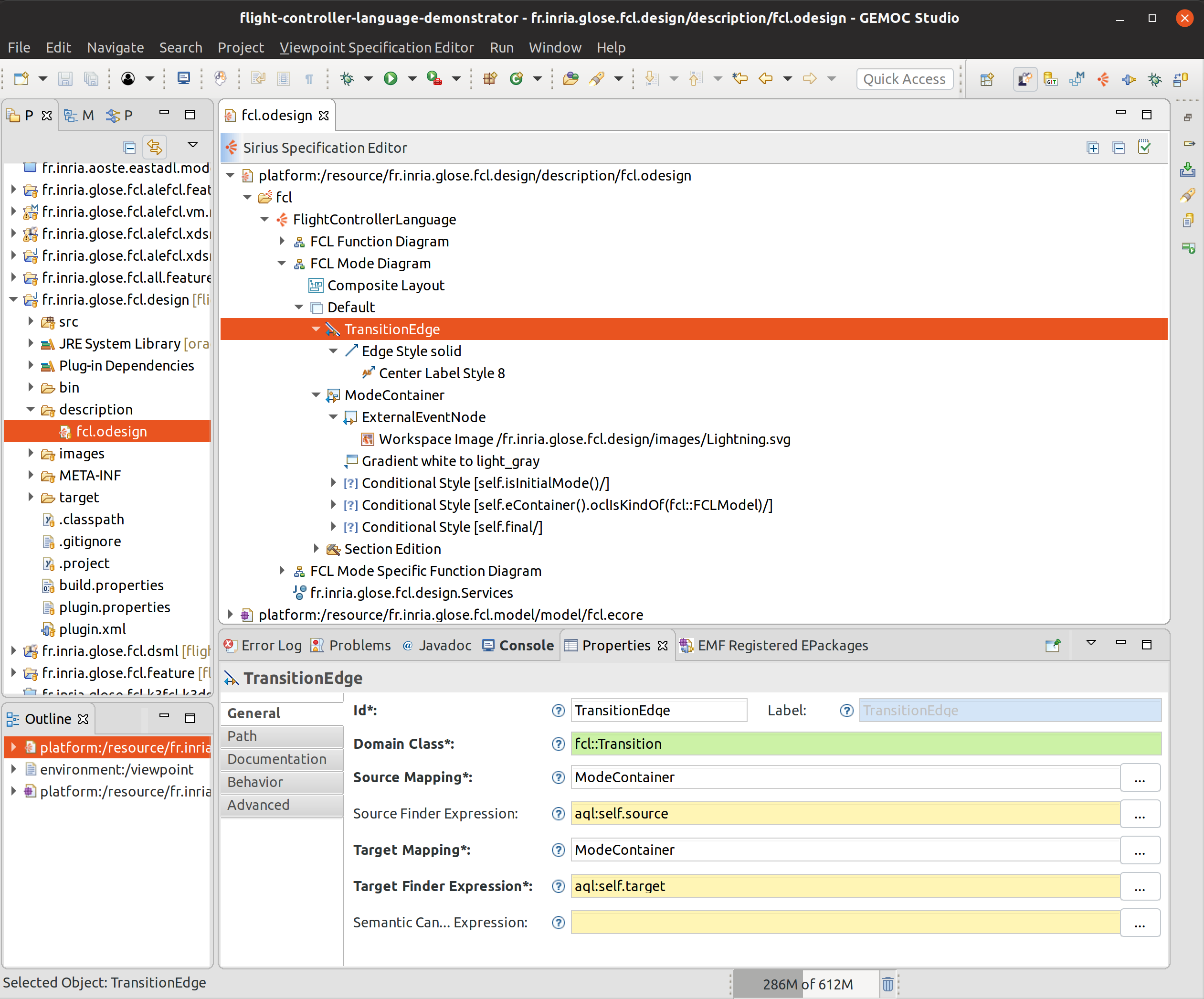
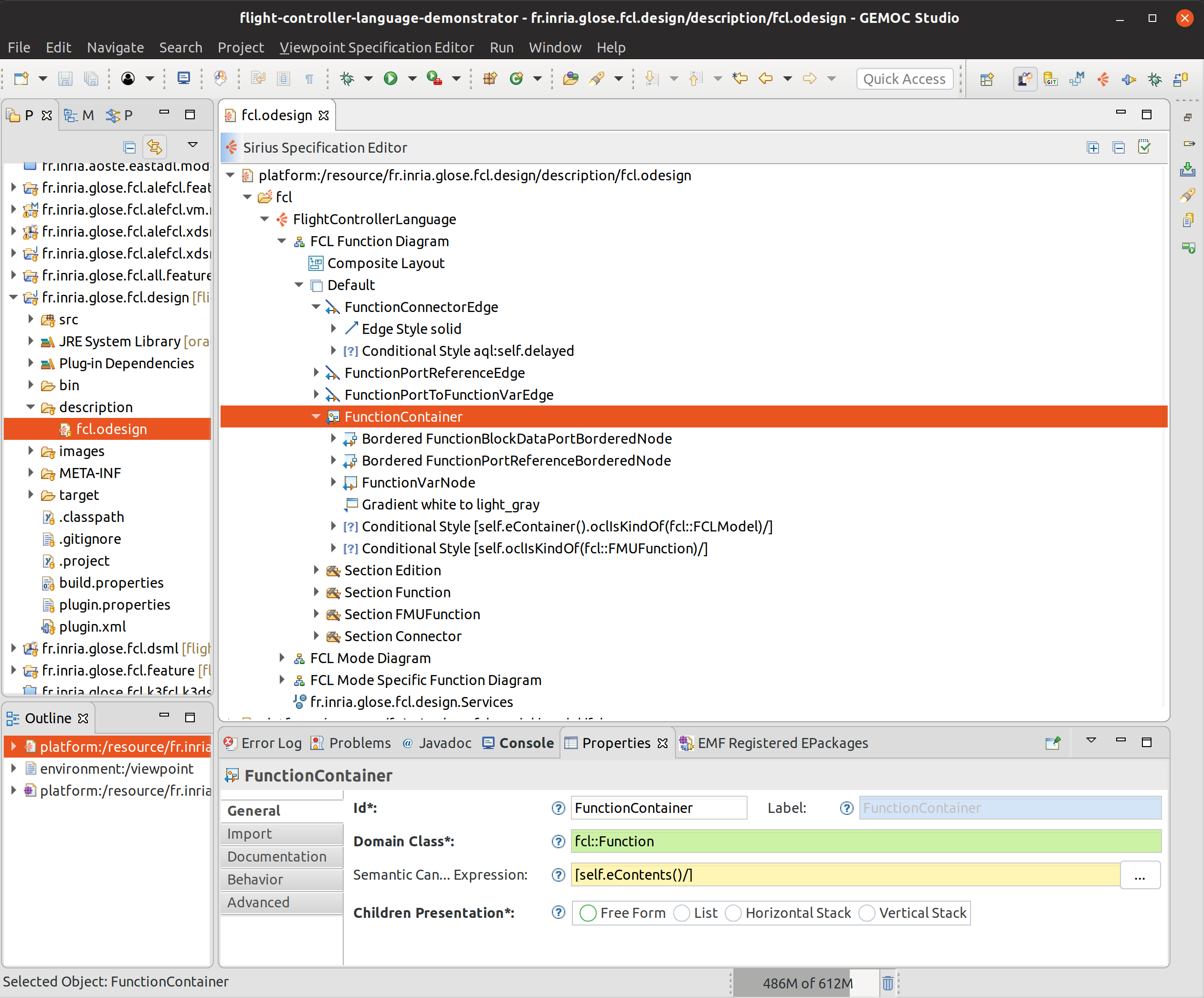
TODO add explanation
Several of the expressions in the odesign are simplified by using a java service. The services are defined in fr.inria.glose.fcl.design/src/fr/inria/glose/fcl/design/Services.java.
|
Reference documentation for writing queries in Sirius: https://www.eclipse.org/sirius/doc/specifier/general/Writing_Queries.html https://www.eclipse.org/acceleo/documentation/aql.html https://www.eclipse.org/acceleo/documentation/ |
⇒ ![]() Section 3.1.2 shows the resulting Sirius editor in action.
Section 3.1.2 shows the resulting Sirius editor in action.
|
Similarly to programming where several programs may produce the same behavior, it exist several ways to write Sirius diagram specification that draw the same diagram. In this demonstrator some attempt have been done to provide correct reuse of the rules and keep the global design simple. However, it can probably be improved. If you see improvement that do not blur the teaching goal feel free to contact the author and propose a change . |
2.2.3. Sirius/Xtext Integration
TODO write section
The java service fr.inria.glose.fcl.design/src/fr/inria/glose/fcl/design/Services.java
defines several methods that helps Sirius/XText collaboration.
For example, the xtextPrettyPrint() (see Listing xtextPrettyPrint java service) that allows to get the XText representation of an EObject
(including its contained element) is very handy to represent Expression in labels.
public String xtextPrettyPrint(EObject any) {
    if (any != null && any.eResource() instanceof XtextResource && any.eResource().getURI() != null) {
        String fileURI = any.eResource().getURI().toPlatformString(true);
        IFile workspaceFile = ResourcesPlugin.getWorkspace().getRoot().getFile(new Path(fileURI));
        if (workspaceFile != null) {
            ICompositeNode node = NodeModelUtils.findActualNodeFor(any);
            if (node != null) {
                return node.getText().trim();
            }
        }
    }
    return "";
}
The method openBasicHoveringDialog(EObject any) is convenient to open a popup window
for long text that doesn’t fit in a label.
The method openTextEditor(EObject any) that allows to open the XText editor is
useful to open the selected element in the text editor.
As the internal EMF resources are connected, saving changes done in the text editor
are automatically taken into account in the graphical editor.
|
XText/Sirius collaboration work correctly only if the user save doesn’t try to do modification both in the textual editor and the graphical editor at the same time. She must save the model before trying to edit using another editor. |
2.2.4. Static Validation
The structure of the metamodel defined in Section 2.1
already provides some guidance to the ![]() Modeler in order to build correct models.
However, this structure cannot capture all non valid situations. Many of them can
be checked early by writing validators.
Modeler in order to build correct models.
However, this structure cannot capture all non valid situations. Many of them can
be checked early by writing validators.
Several technique are possibles (OCL, Sirius validation rule, Xtext validation framework, EMF validation framework).
In this demonstrator, as it relies on Xtext for the serialization, we’ve implemented a set of check rules using Xtext framework which is very easy to set up. They are in the following file fr.inria.glose.fcl.xtext/src/fr/inria/glose/fcl/validation/FCLValidator.xtend.
They cover:
-
type checking of Expression and Action
-
checking of call/assignment of properties in complex data types
-
checking of number of parameter when calling a Procedure
-
checking of initial value on variables
-
checking of loop connection (ie. InOut ports that have a connection to themselve which are valid only if the connector is delayed, that it, its value is transmitted only when finishing the parent function)
|
Many other useful check rule could be written, the In some case, the check might be only some advice reported as warning. For example, in FCL,
a rule report a warning when 2 different types are compatibles but combined (or assigned) together.
This helps the |
2.3. Behavioral Semantic and Debugger Design
TODO Write section explain ALE, explain FCL behavior
2.4. FCL Animation
The Sirius diagram animation specification is in fr.inria.glose.fcl.alefcl.xdsml.design project.
It extends the fr.inria.glose.fcl.design project (see Section 2.2.2) by adding new layers.
A first layer Debug has been added to support interaction with the GEMOC debugger. It role is to provide:
-
breakpoint representation and actions (toggle breakpoint),
-
engine interaction, allowing to start an execution
-
execution stack highlighting (ie. when clicking a step in the execution stack, it highlights the step target model elements)
A second layer Animation has been added to support domain specific (FCL) animation directly on top of the model diagrams.
|
As the graphical representation for FCL is composed of 2 diagrams (Mode and DataFlow), the new layers Debug and Animation must be specified in each of these diagrams. |
2.5. Extra views
The demonstrator also provide a FCL specific view: FCL External Ports View.
This view is built as an eclipse UI view that registers to the execution as a GEMOC engine addon dedicated only to FCL.
This view is designed to show only the outer FunctionPorts of the running model.
It also allows to modify the values of these FunctionPorts.
The java code of this view is in the fr.inria.glose.fcl.alefcl.xdsml project.
-
ExternalPortsView.java contains the code for the UI
-
ExternalPortsViewAddon.java is the addon that listen for GEMOC engine event and trigger an update of the view.
-
plugin.xml registers the view to Eclipse UI and registers the addon to the GEMOC Engine specifically for FCL language.
2.6. Deployment
The modeling environment can be deployed using several way:
-
for development purpose, a runtime workbench is started from the language workbench. It allows to test and debug the language tooling.
-
for use by the final end user (ie. the
 Modeler), the projects can be packaged
and installed directly in an Eclipse product.
Modeler), the projects can be packaged
and installed directly in an Eclipse product.
2.6.1. Packaging and Deployment in an Eclipse Product
TODO write section
2.6.2. Runtime Deployment
To get a runtime deployment for testing a language:
-
Run → Run configurations… → Right click on Eclipse Application → new configutation
This creates a launch configuration that runs a new Eclipse similar to the current one but also that also includes the plugins under development in the workspace.
3. Scenario #2: Simulating and Debugging a Behavioral Model
This scenario demonstrates the ability of the GEMOC Studio to provide a full-fledged modeling and execution environment, that supports a language user (i.e., a domain expert, being a systems engineer in the case of the chosen use case) in the design and early validation & verification of a complex system. This scenario shows how to edit a model, and execute it such as the language user can interact with it to inject external stimuli through the event manager and drive the execution accordingly. In addition, the scenarios demonstrates the various facilities provided to help manually debugging the model (wrt. to an expected behavior), such as breakpoint definition and time traveling (forward and backward).
3.1. Model Edition
The Modeling workbench designed in Chapter 2 offers several model editors.
3.1.1. Textual Editor in Action
The smallest valid FCL model would be similar to Listing smallest FCL model. With a single mode and a main function that does nothing.
FlightControllerModel SmallestController {  (1)
    mainModeStateMachine {
        mode ManualAcrobaticFlight {}       (2)
        initialMode ManualAcrobaticFlight   (3)
    }
    mainFunction {                          (4)
    }
}| 1 | name of the model |
| 2 | definition of a mode |
| 3 | definition of the initial mode |
| 4 | main function |
A slighty more complex example would look like Listing Small FCL model with one master function. It defines
FlightControllerModel SmallController {
    mainModeStateMachine {
        mode ManualAcrobaticFlight {}
        initialMode ManualAcrobaticFlight
    }
    mainFunction {
        ports {
            dataPort in i : integer defaultValue 0  (1)
            dataPort out o : integer
        }
        action {
            o := (i * 10)                           (2)
        }
    }
    dataTypes {
        IntegerValueType integer {}                 (3)
    }
}| 1 | the master function exposes an input port i and an output port o |
| 2 | the action indicates how to compute o |
| 3 | the model defines an integer type |
And a minimal system that defines several modes will look like Listing Minimal FCL model with modes.
FlightControllerModel minimalController {
    mainModeStateMachine {
        mode MultBy10 {
            enabledFunctions (X10)          (1)
        }
        mode MultBy100 {
            enabledFunctions (X10)          (1)
        }
        final mode Stop {}                  (2)
        initialMode MultBy10

        transition MultBy10 -> MultBy100 { when buttonPressed } (3)
        transition MultBy100 -> Stop { when buttonPressed }
    }
    mainFunction {
        ports {
            dataPort in i : integer defaultValue 0
            dataPort out o : integer
        }
        dataFlow {                          (4)
            function X10 {
                ports {
                    dataPort in ix10 : integer defaultValue 0
                    dataPort out ox10 : integer
                }
                action {
                    ox10 := (ix10 * 10)     (5)
                }
            }
            function X100 {
                ports {
                    dataPort in ix100 : integer defaultValue 0
                    dataPort out ox100 : integer
                }
                action {
                    ox100 := (ix100 * 100)  (5)
                }
            }
            connect X10.ox10 <-> o          (6)
            connect X100.ox100 <-> o
            connect i <-> X10.ix10
            connect i <-> X100.ix100
        }
    }
    events {
        external buttonPressed              (7)
    }
    dataTypes {
        IntegerValueType integer {}
    }
}| 1 | each mode indicates which sub function is active or not. |
| 2 | some mode may be final to end the execution. |
| 3 | transitions between modes. (can be triggered via events and/or guard on data). |
| 4 | the main function declares 2 sub functions (in this case they are exclusive). |
| 5 | each sub function declare an action indicates how to compute its output. |
| 6 | mapping between ports (in this case between child functions to parent functions, but this can also be between 2 children functions). |
| 7 | an event that can be raised (either internally from an action or from the system environment). |
3.1.2. Graphical Editor in Action
Opening the Sirius representations of the minimal controller Listing Minimal FCL model with modes provide the diagrams of Figure 14.
MinimalController-Sirius-editor-Screenshot.png
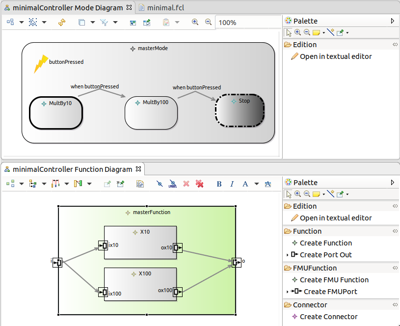
TODO write section
Figure 12 and Figure 16 show the graphical editor diagrams applied to the Quadcopter demo controller.
3.1.3. Static Validation
The validation rules added in [sec-fcl-static-validation] are reported in the Modeling workbench in several ways:
-
directly in the editors using colored icons; (hovering over the element shows a tooltip with an explanatory text.)
-
in a summary in the Problem view
TODO show some error and warning in the various views
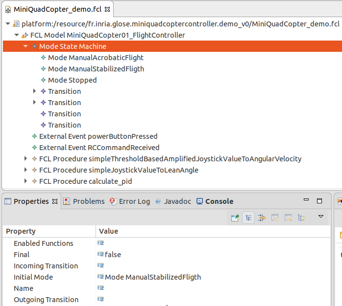
3.1.4. Basic Tree Editor in Action
As seen in Section 2.1.2, a simple tree editor is also available.
since we haven’t generated the dedicated java code for it, the ![]() Modeler can open
a fcl file using a Right click on the .fcl file → Open With → Other →
Sample Reflective Ecore Model Editor
Modeler can open
a fcl file using a Right click on the .fcl file → Open With → Other →
Sample Reflective Ecore Model Editor
Figure 17 shows this tree editor on the basic quadcopter controller.
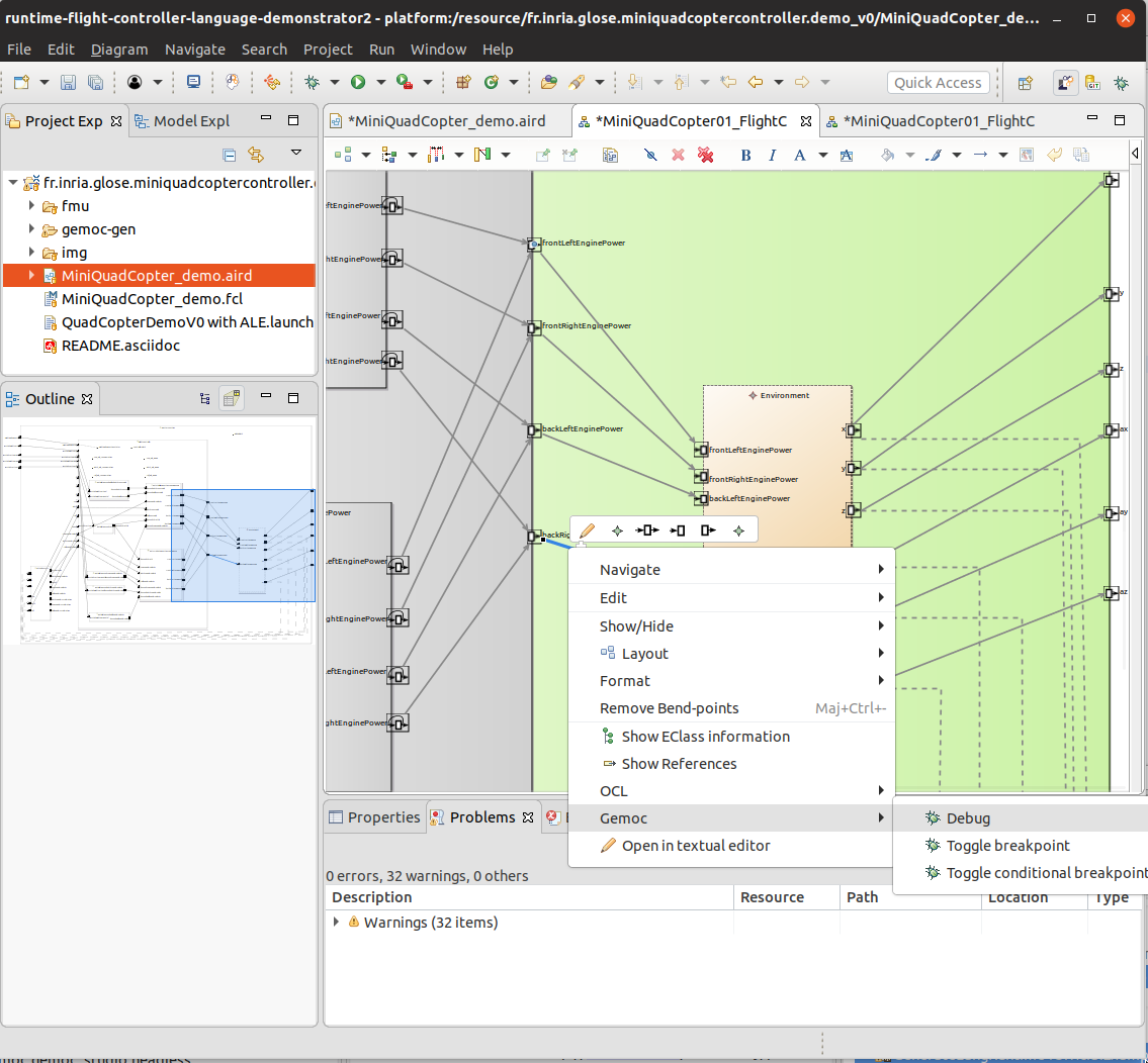
3.2. Debugger in Action
Figure 18 shows the toggle breakpoint action and some elements with the breakpoint icon that is provided by the Debug layer.
3.3. Animation in Action
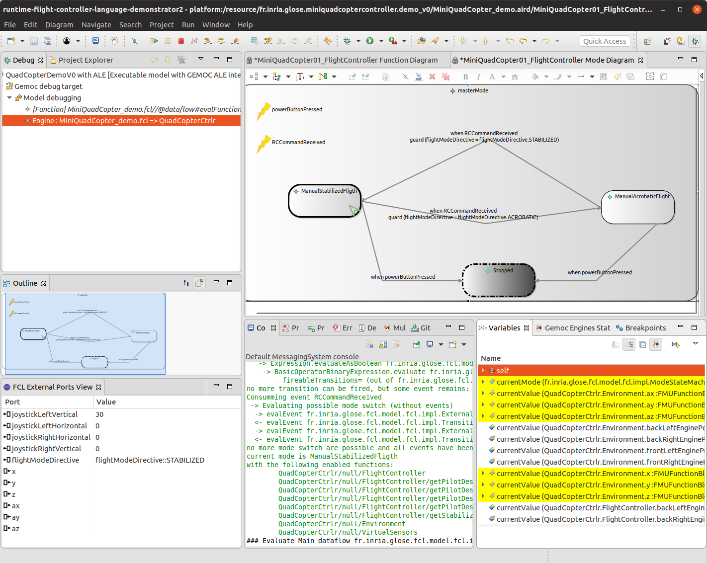
Figure 20 shows the the demo controller model running and paused having evaluated all functions one time. The FCL External Ports view displays the current value of the port located on the MasterFunction (ie. the outer function)
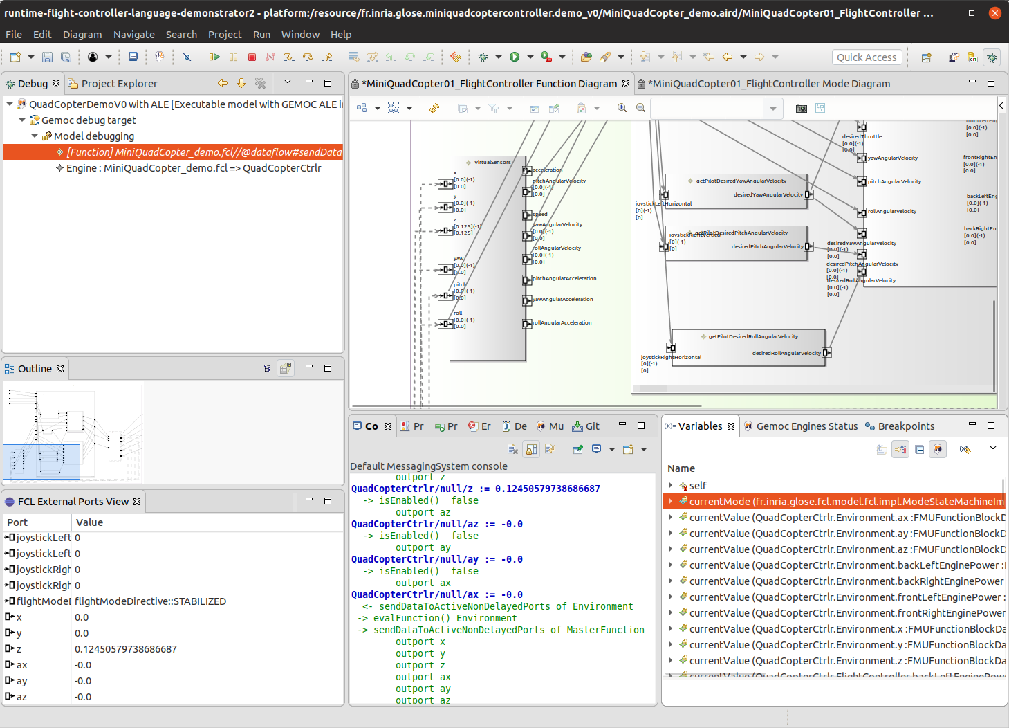
Figure 21 shows how a double click (or right click → popup menu → Change Value) in the FCL External Ports view allows to changes its value.
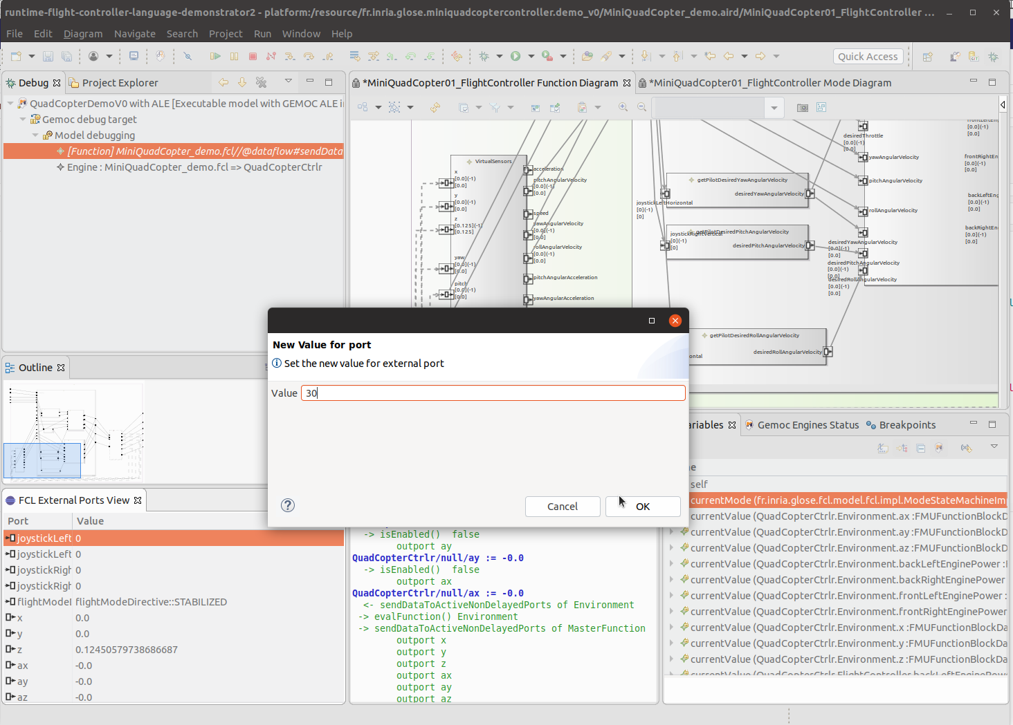
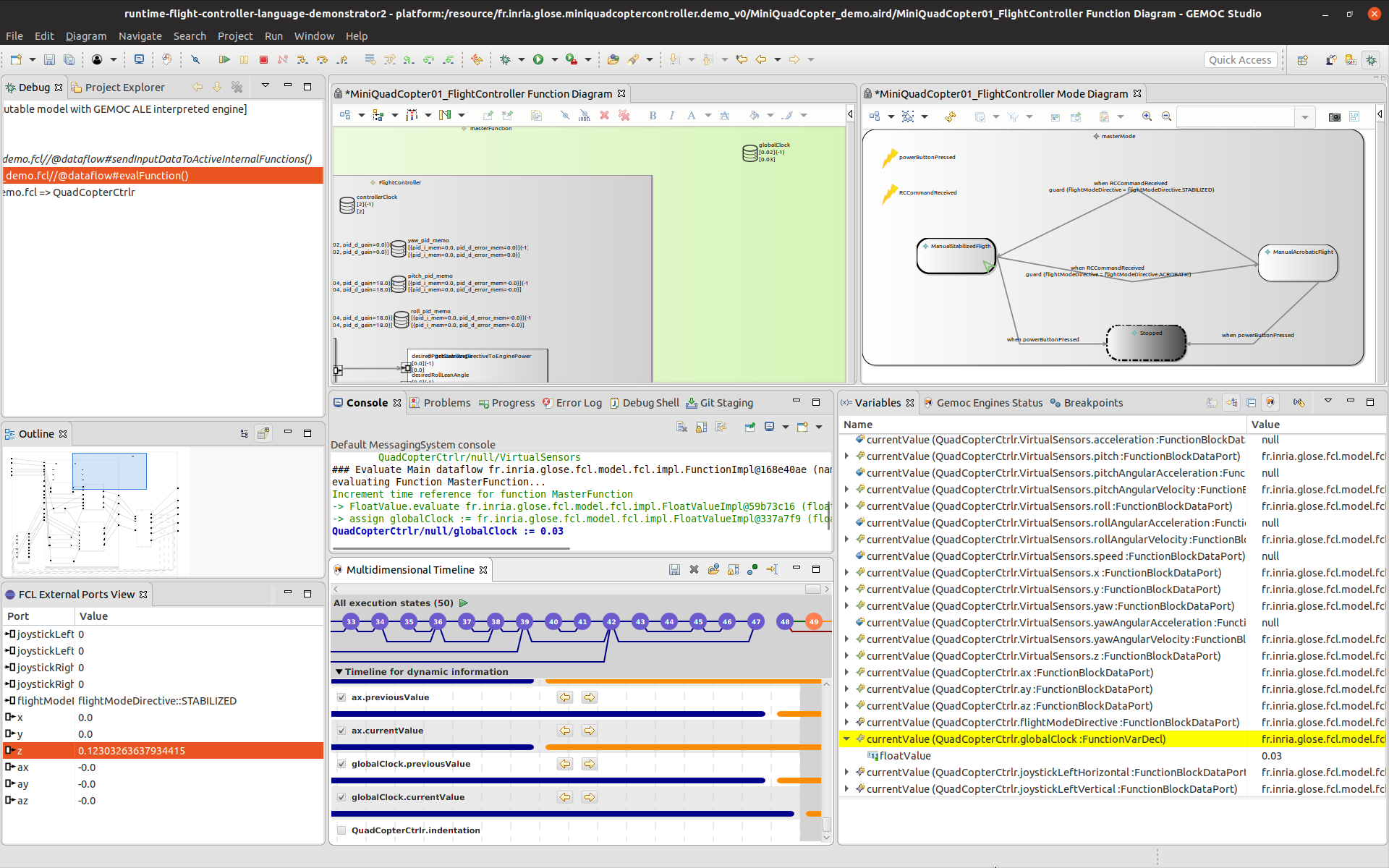
Figure 22 shows the Demo controller paused after an update of the global clock. The Multidimensional timeline shows the changes on the current value. The value is also visible in the Variables view and the Sirius diagram.
4. Planning for V2
The version 1 of the demonstrator will be enhanced into a V2.
Most of them are listed in the gitlab: https://gitlab.inria.fr/glose/flight-controller-language-demonstrator/issues
4.1. Enhancement of Existing Features
4.2. New Features
-
Concurrent Engine
-
Scenario #3: Exploring the Design Space of a Behavioral Model This scenario will demonstrate the ability of the GEMOC Studio to explore the possible execution paths allowed by the model. As an outcome of such a scenario, the demonstrator will show how to record external stimuli as generic scenarios and reuse them as test cases.